For engineers, hobbyists, and automation technicians who have ever built a mechanical system driven by motion, the traditional parts inventory is a familiar and frustrating hurdle. Designing a multi-axis motion system has historically required sourcing and assembling a disparate pile of hardware: a stepper motor or brushless direct current (BLDC) motor, an external driver board, a separate motion controller to generate step-and-direction commands, an optional encoder to verify actual physical displacement, and an intricate, messy loom of wires connecting all of these distinct components together.
Today, however, the landscape of small-to-medium scale automation is shifting rapidly toward a streamlined alternative known as the integrated servomotor. By collapsing this complex stack into a single, cohesive housing that combines the motor, driver, motion controller, and encoder into one unit, manufacturers are redefining how motion systems are designed, wired, and deployed.

Anatomy of an Integrated Servomotor
At its core, an integrated servomotor eliminates the boundaries between mechanical power generation and electronic control. In traditional setups, the motor is a passive electromagnetic component that simply reacts to whatever power the external driver supplies. The driver interprets signals from a controller, while a rotary encoder mounted to the rear shaft reports position data back to that controller, completing a feedback loop that might involve three different manufacturers and multiple points of failure.
An integrated unit internalizes this entire ecosystem. The distinguishing feature of any true servomotor—integrated or otherwise—is the continuous closed-loop feedback mechanism. Unlike open-loop stepper motors, which operate on the blind assumption that every electrical pulse successfully translates to a physical step, an integrated servo constantly measures its actual position against its commanded position. If the motor encounters mechanical resistance, a sudden snag, or an acceleration command that is too aggressive for its torque limits, the internal controller detects the error in real-time and dynamically applies corrective torque.
By housing the microcontroller, power electronics, and sensing elements directly on or inside the motor chassis, manufacturers eliminate signal degradation over long wire runs between the driver and the motor, while drastically shrinking the hardware’s spatial footprint.

Transitioning from the Classic Stack to Integrated Units
The architectural differences between conventional motion stacks and modern integrated units become starkly apparent when evaluating system complexity, particularly as the number of axes scales upward.
| The Classic Stack | The Integrated Unit |
|---|---|
| Motor, driver, controller, and encoder sourced from up to 3 different vendors | A single self-contained part backed by one comprehensive datasheet |
| Individual STEP/DIR wiring harnesses per axis alongside dedicated encoder cabling | A single multi-drop bus cable connecting devices in a daisy-chain topology |
| Manual tuning of current limits, microstepping, and PID loops | Factory-calibrated tuning optimized specifically for the matched internal motor |
| Diagnostic ambiguity: determining which of several interconnected parts failed | A singular component to test, troubleshoot, or swap out |
In multi-axis machinery—such as a 6-axis robotic arm, a multi-head CNC router, or an automated laboratory liquid handler—the wiring advantages of integrated units compound exponentially. A traditional 6-axis machine driven by legacy STEP/DIR signals can easily require dozens of individual conductors running through cable carriers, creating significant points of failure and maintenance nightmares.
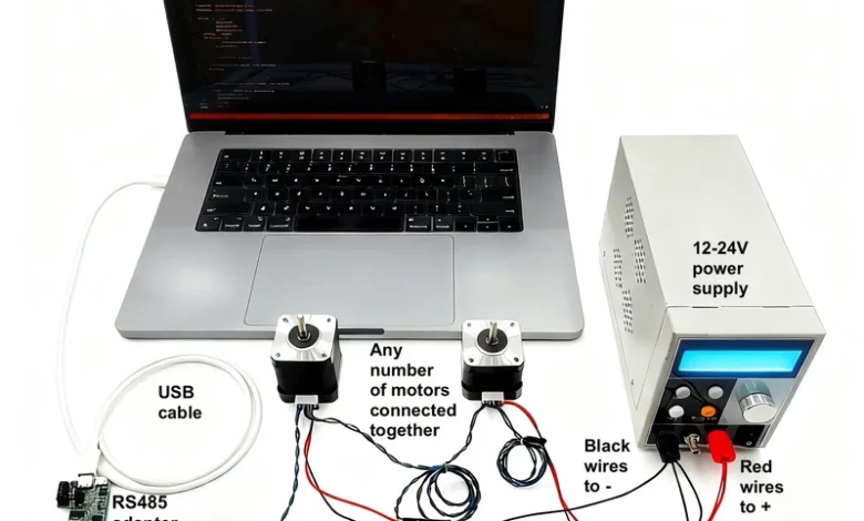
By contrast, modern integrated servomotors frequently utilize robust multi-drop communication buses, such as RS-485, CANopen, or industrial Ethernet variants. In an RS-485 implementation, for example, a single twisted-pair cable can visit each motor in a daisy-chain configuration. Every unit is assigned a unique software address, allowing a single host controller to communicate bidirectionally with every motor on the network through one physical port.

Real-World Applications and the M17 Paradigm
To understand how this technology manifests in current hardware engineering, one can examine recent developments in the NEMA-17 form factor—a ubiquitous standard in 3D printing, small robotics, and compact automation. Industry developers have begun introducing open-hardware solutions designed to bring industrial-grade closed-loop performance to desktop and commercial devices at accessible price points.
A prominent example of this movement is the M17 family of integrated servomotors developed by engineering firms like Gearotons. Designed around the standard NEMA-17 mounting footprint, these units incorporate closed-loop servo control, RS-485 daisy-chain communication, and fully open-source hardware, firmware, and software stacks. Aimed at developers utilizing Python and Arduino, these systems even incorporate modern developer tooling, such as Model Context Protocol (MCP) servers, enabling natural language AI control environments like Claude Code to command physical hardware tasks.
Operating within a power rating of roughly 25 to 38 watts and delivering un-geared holding torques around 0.65 N·m depending on the specific model variant, such motors are optimized for desktop automation, scientific instruments, and lightweight gantry systems.

Evaluating the Trade-offs: When to Choose an Integrated Servo
Despite their clear advantages in wiring simplicity and spatial efficiency, integrated servomotors are not a universal replacement for every motion application. Engineering design requires an honest assessment of trade-offs:
- Thermal Management: Cramming microprocessors, power MOSFETs, and motor windings into a single compact enclosure concentrates heat generation. In continuous high-load applications, thermal dissipation can become a limiting factor compared to remote-mounted drivers equipped with large external heatsinks or forced-air cooling.
- Environmental Robustness: Many commercial integrated units—including entry-level open-source variants—are rated around IP20, meaning they lack robust sealing against moisture, coolant sprays, or fine conductive dust found in heavy industrial machining environments.
- Cost vs. Simplicity: While integrated units reduce labor costs associated with wiring harnesses and troubleshooting, the upfront cost per axis can be higher than a bare-bones open-loop stepper motor paired with a cheap generic driver board.
- Power Limitations: Integrated units excel in small-to-medium form factors (such as NEMA-14, NEMA-17, and NEMA-23). For heavy industrial axes requiring kilowatts of power, traditional separate high-voltage servo drives and large servomotors remain the industry standard due to thermal and electrical isolation requirements.
Broader Industry Implications and Future Outlook
The evolution of integrated servomotors reflects a broader trend across industrial automation and embedded systems: edge intelligence and modularity. By embedding processing power directly at the actuator level, modern motion control is shifting from centralized architectures—where a massive central PLC calculates every micro-step and monitors every sensor—to decentralized, intelligent networks where individual motors act as smart nodes capable of local trajectory planning, fault detection, and telemetry reporting.
As open-source hardware principles increasingly merge with industrial automation protocols, developers across sectors from biotechnology to advanced manufacturing can expect shorter prototyping cycles and more resilient mechanical systems. Whether an engineer is building an automated laboratory workstation or a multi-axis experimental rig, understanding when to deploy an integrated servomotor—and recognizing its physical limitations—has become an essential competency in modern mechanical and electronic design.